Nemokamas standartinis pristatymas užsakymams virš $9.9
Grąžinimo politika
Prekės priimamos grąžinti per 40 dienų nuo gavimo datos. Individualios prekės negrąžinamos. Prekės įsigytos su dovanų kuponu gali būti tik keičiamos; grąžinimas negalimas.
Nemokama Dovana
Sveiki atvykę į Roymall, jūsų profesionalią dovanų parduotuvę. Vertiname jūsų paramą ir norėdami parodyti dėkingumą, siūlome nemokamą dovaną su kiekvienu užsakymu.
Pristatymo Politika
Prekės pristatomos per 2-5 darbo dienas. Užsakymai virš $9.9 pristatomi nemokamai.
1. Grąžinimo Politika
Prekės galima grąžinti per 40 dienų. Individualios prekės negrąžinamos.
2.Grąžinimo Sąlygos
Pinigai grąžinami originaliu apmokėjimo būdu.
Videos for similar product
Loading product videos...
❮
❯
Products related to this item
Loading related products...
❮
❯
Description:
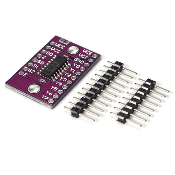
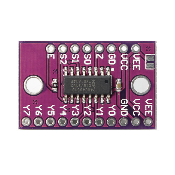
74HCT4051 is a single-pole octal-throw analog switch (SP8T) suitable for use in analog or digital 8:1 multiplexer/demultiplexer applications. The switch features three digital select inputs (S0, S1 and S2), eight independent inputs/outputs (Yn), a common input/output (Z) and a digital enable input (E). When E is HIGH, the switches are turned off. Inputs include clamp diodes. This enables the use of current limiting resistors to interface inputs to voltages in excess of VCC.
Features:
Wide analog input voltage range from -5 V to +5 V Complies with JEDEC standard no. 7A Low ON resistance: 80 ohm (typical) at VCC - VEE = 4.5 V 70 ohm(typical) at VCC - VEE = 6.0 V 60 ohm(typical) at VCC - VEE = 9.0 V Logic level translation: to enable 5 V logic to communicate with± 5 V analog signals Typical u2018break before make' built-in ESD protection: HBM JESD22-A114F exceeds 2000 V MM JESD22-A115-A exceeds 200 V CDM JESD22-C101E exceeds 1000 V Multiple package options Specified from -40℃ to +85℃ and -40℃ to +125℃
Package included:
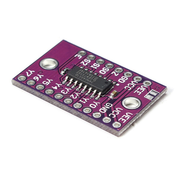
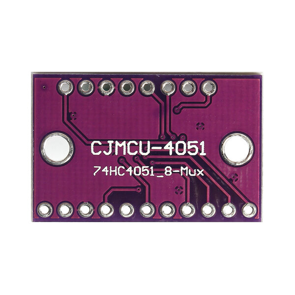
1 x CJMCU-4051 74HC4051 8 Channel Analog Multiplexer Module
This chip is ideal for connecting more than one analog input/output to the Arduino ESP8266 (which supports only one analog port). For this purpose you connect GND+VCC as usual and... Pin Z to A0 / Y0-Y7 to up to 8 analog devices / S0-S2 to 3 digital ports on the Arduino (binary switching the analog ports 0-7) / E to LOW/GND to enable Switches (see datasheet). The description lacks the supply voltage VCC which is 2V up to 10V and the data sheet which you can find at http://www.farnell.com/datasheets/1645588.pdf