Specifications:
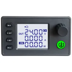
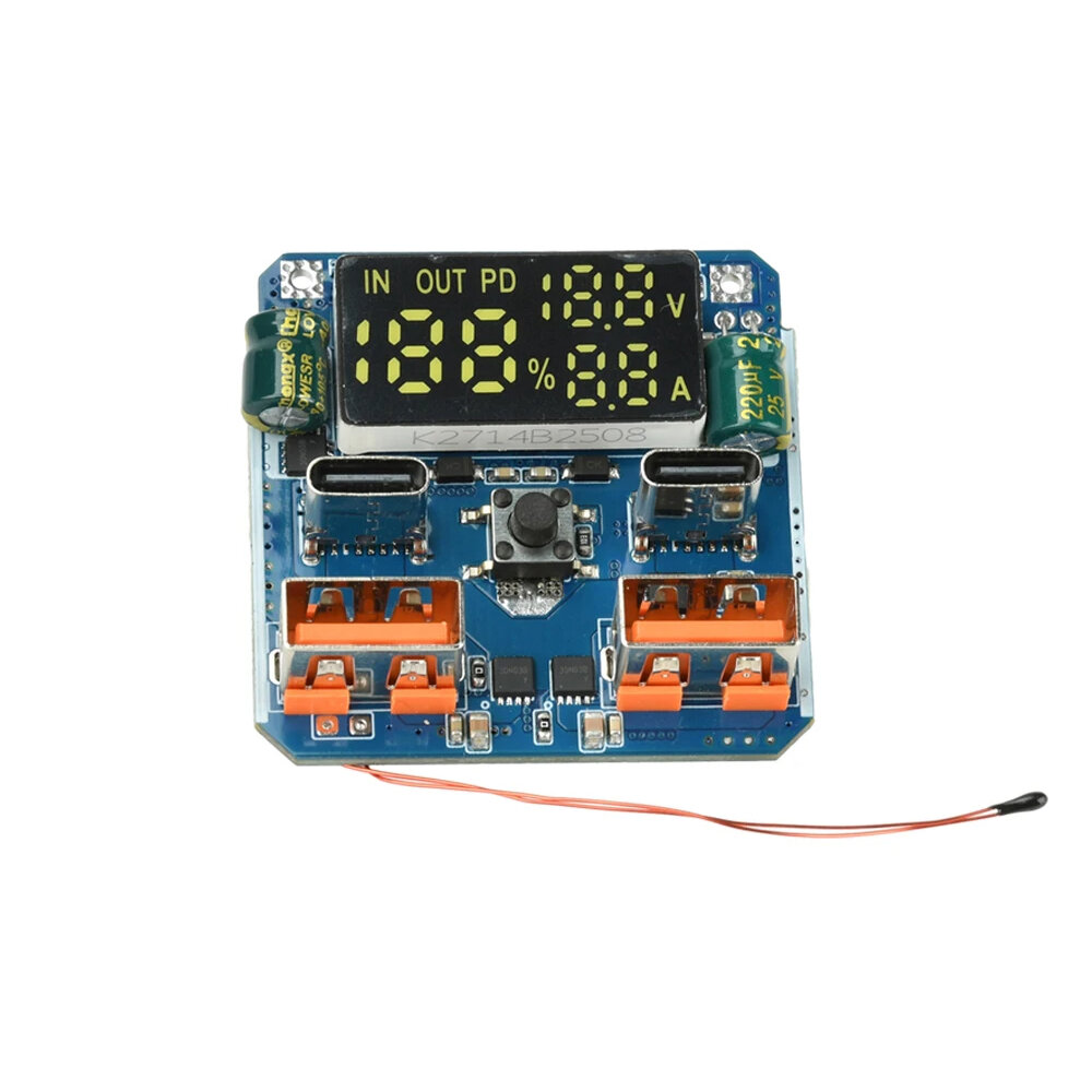
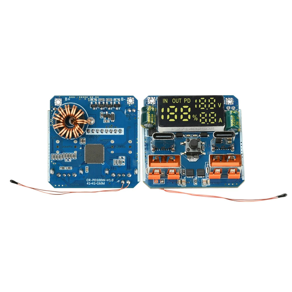
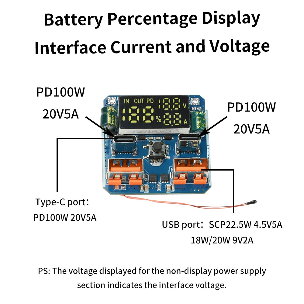
Input/Output Type-C Port: PD100W, 20V/5AUSB Ports: SCP 22.5W (4.5V/5A), 18W/20W (9V/2A)Current/Voltage Display: Built-in screen for clear real-time monitoringBattery Percentage Display: Accurate tracking of battery levelsCompatible Battery Type: Lithium battery systems
Features:
1) Lithium Battery Compatible: Ideal for use with lithium battery systems.2) Buck-Boost Integrated: Supports both step-up and step-down voltage conversion.3) Fast Charging: Enables rapid charge and discharge cycles for time-saving operations.4) 4S PD 100W: High-power charging and discharging for fast energy transfer.5) 20V 5A Output: Delivers stable and efficient high-current performance.
Package Included:
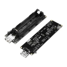
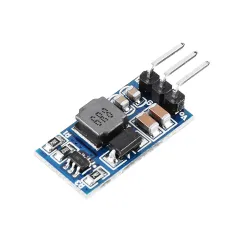
1 x Integrated Buck-Boost Module
Precautions:1. Do not solder while the circuit is powered on. When soldering the + and - wires on the mainboard, these wires should be de-energized to avoid 99.99% of potential accidents.
2. The mainboard only has + and - wires. Please solder with the power off. Connect the mainboard + and - wires first. Solder the negative terminal of the battery pack last! The two wires on the mainboard cannot balance the battery charge; the balancing protection function is on the lithium battery protection board.
3. The battery charge display may not be accurate on the first power-on. It will return to normal after a cycle.
4. The default capacity is 500mAh per cell. Significant differences may occur, which may cause inaccurate charge display. This does not affect other functions, so there is no need to worry about overcharging or over-discharging.
Frequently Asked Questions:1. The battery level may not display correctly on the first power-on; it will return to normal after a cycle.
2. The default capacity is 500mAh per cell, and the display may be inaccurate due to significant differences. This does not affect other functions, so there is no need to worry about overcharging or over-discharging.
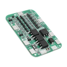
3. For the protection board wiring, with a 4-cell battery pack, starting from the negative terminal, the first positive terminal is b1 (4.2V), followed by b2 (8.4V), b3 (12.6V), and b+ (positive terminal) (16.8V).
4. Connect the P+P terminals of the protection board to the positive and negative terminals of the main board.
5. The voltage between b1 and the negative terminal is 4.2V.
6. If the battery has power but does not light up or work after connection, please charge the C port to activate it. Even if the battery has no power, it needs to be charged to activate it.




 Roymall C.o.


 Kado gratis
 Règleman livrezon
 Règleman retou








 Coupon Code
 Direct purchase from the factory
 Electronic Components & Supplies
 Module Board
 Boost & Buck Module